PIXL (Planetary Instrument for X-Ray Lithochemistry)
mission specific
Instrument Overview
PIXL (Planetary Instrument for X-ray Lithochemistry) is a microfocus X-ray fluorescence instrument that measures elemental chemistry at sub-millimeter scales. This is achieved by focusing an X-ray beam to a small spot ~ 150 µm, scanning the surface with this beam, and then measuring the induced X-ray fluorescence. Since PIXL also contains a micro-context camera (MCC) it correlates sub-mm scale geochemistry with surface texture.
PIXL is mounted on the rover’s robotic arm, allowing it to be placed in close proximity to the surface of selected science targets. For additional precision in placement, and to correct for drift in the robotic arm positioning, PIXL’s mounting to the arm includes an articulated hexapod system, allowing PIXL’s position in space to be finely adjusted.
In addition to the PIXL Sensor Assembly mounted on the robotic arm, the instrument includes its own electronics system with an instrument computer and memory module, mounted inside the rover body. PIXL is also furnished with a calibration target, mounted externally to the rover in reach of the arm.
PIXL observations consist of a suite of X-ray fluorescence measurements, context images, and metadata. The XRF measurements can be executed in a variety of geometries depending on target type and available observation time, and are accompanied by a set of images documenting the target and its position relative to the instrument.
The PIXL Electronics Box is located inside the Rover on the RAMP, the PIXL Sensor Assembly is located on the Rover Turret, and the PIXL Calibration Target is located on the robotic arm (RA) shoulder azimuth joint. See the figures below for the approximate locations.
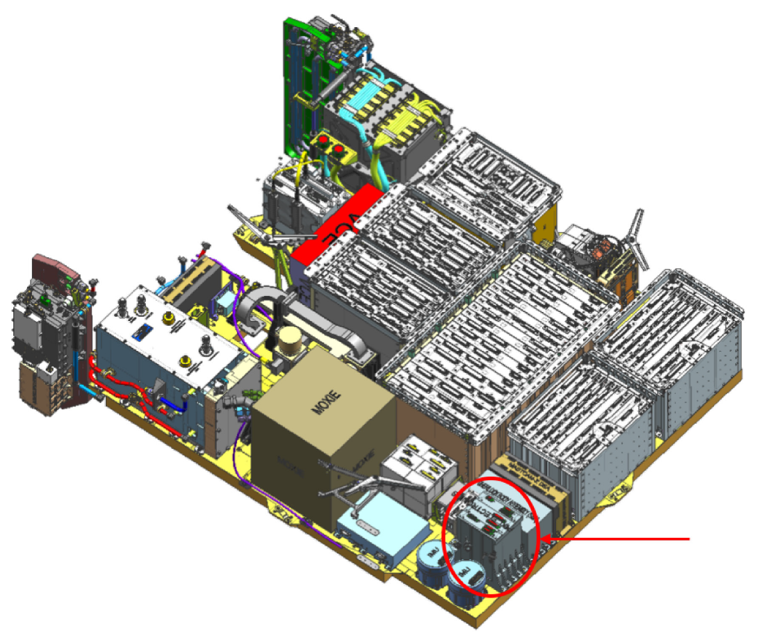
PIXL Electronics location on the RAMP. The electronics consists of an instrument computer and memory module, mounted inside the rover body.
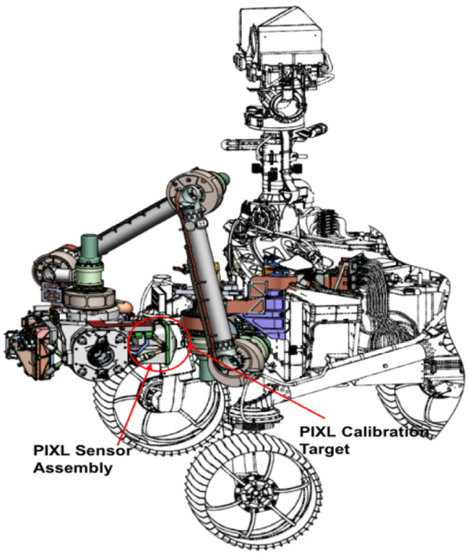
PIXL Sensor Assembly and Calibration Target locations on the robotic arm.
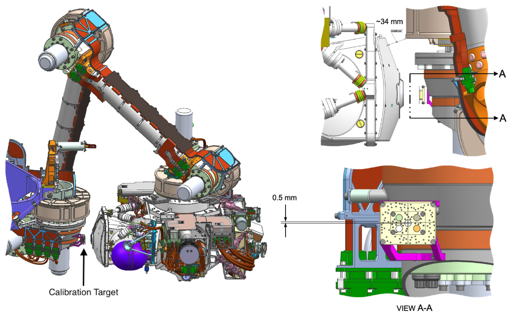
The location of the PIXL calibration target.
PIXL Sensor Assembly
The PIXL Sensor Assembly houses the primary sensors, detectors and X-ray source used for PIXL science measurements. Specifically, the Sensor Assembly houses the 28 kV High Voltage Power Supply (HVPS) which contains both a High Voltage Multiplier Module (HVMM) and a Low Voltage Control Module (LVCM). This system energizes the X-ray tube which focuses the resultant X-rays through the X-ray optic and onto the target surface. Two Silicon Drift Detectors (SDD) collect the X-rays fluoresced from the target, enabling chemical analysis of the surface. A key metric for interpreting fluoresced flux and focusing the X-ray spot onto the surface is a distance measurement to the surface. The PIXL Optical Fiducial system (OFS) enables the measurement of surface distance. This system utilizes a coarse and fine structured light illuminator (SLI), which is a device that shines laser spots onto the target in a specific pattern (coarse or fine). A high resolution black and white camera - the micro context camera (MCC) - is then used to take a picture of the surface with the laser pattern illuminating the surface. The PIXL Instrument Flight Software (iFSW) uses this information to determine the distance to the target surface at the location of the X-ray spot. The sensor head is mounted onto the turret with isolation struts and 6 active struts that provide x, y, and z motion completing the sensor assembly (sensor head + active hexapod). The active hexapod is driven by the needs to: scan the surface for a map, correct for any placement errors or drift errors from the Robotic Arm, and to focus the X-ray spot on the surface based on the distance to the target. The sensor assembly also has a dust cover that is controlled with a motor very similar to the motor used in the active struts (just smaller).
PIXL has a set of heaters on the Sensor Assembly. The survival heaters continually cycle to keep the HVMM within its required temperature limits. These heaters are on two circuits, and one is always asserted on. One is primary, and one is redundant. A PIXL temperature control board is used to cycle the heaters and, as a fall back, the heaters are controlled with mechanical thermostats. Other heaters for pre-warming the LVCM and the AFE are activated to bring the devices up into operational AFT limits.
PIXL's robust science operations are enabled by the PIXL iFSW. The PIXL iFSW controls all mapping, imaging, hexapod movement - basically all PIXL functions. So, the computing for PIXL operations is performed internally by PIXL, and the rover FSW will essentially send pass through commands with arguments that define what the PIXL iFSW will do.
The PIXL Optical Fiducial System (OFS)
To ensure the measured chemistry is unambiguously tied to the textural features in the targets, PIXL has an optical fiducial system (OFS) co-aligned with the X-ray beam (see figure below).
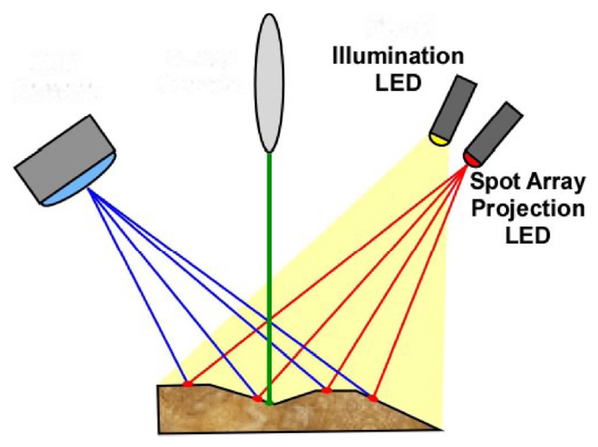
Alignment of the OFS (the MCC in blue, Spot LED in red) with the PIXL X-ray beam (in green).
The OFS consists of a micro-context camera, multi-color flood illuminator, and an LED illuminator that projects reference spots onto the target.
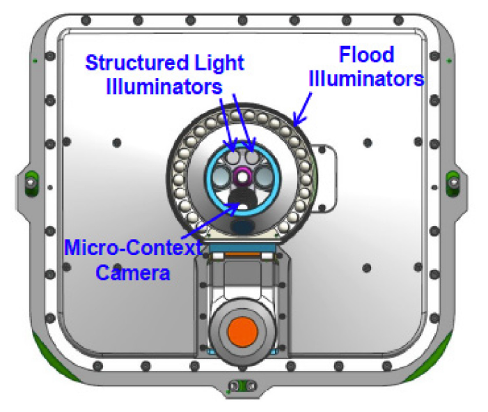
The location of the OFS components in the head of the PIXL Sensor Assembly.
The arrangement of color LEDs in the flood illuminator are shown in the figure below. Together these are used to acquire visible images of the sample and enable visual registration of the position of the X-ray beam. The Micro-Context Camera has a spatial resolution of 50 μm per pixel and a field of view of 29 x 36 mm. This allows observations of textural features and microstructures as small as PIXL's X-ray beam, across an area of similar size to an abraded patch produced by the surface preparation tool on the rover. While an image is being taken, an array of light spots will be projected onto the sample surface. The spot array has a fixed geometric relationship to the X-ray beam to provide a means of spatially correlating measured chemistry to observed visual features as well as making a map of the rock topography.
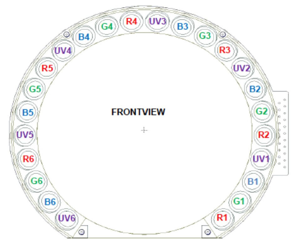
Color arrangement within the flood illuminator
PIXL Electronics
The PIXL electronics contain 3 FPGAs and a LEON3 processor. While the RCE has the ability to send basic commands to PIXL by sending a limited number of pass-through commands to the FPGA (typically only in iFSW fault cases), nominally all commanding and functions will be controlled with PIXL via the iFSW and the FPGA. Therefore, RCE commanding is quite limited and straightforward. Most RCE commanding will be done using the SEND_DATA and ACQUIRE_DATA commands. Note that the MCC camera electronics are inside the Rover as well and mate directly to the PIXL Electronics. The algorithms for localization reside on the MCC electronics but interface back to the PIXL iFSW. PIXL generates a large amount of data during operations, and while not all of this data will get sent to the Rover and back to earth, it is all stored internally within PIXL. PIXL has 8GB of flash which is likely sufficient to store all observations for the life of the mission.
PIXL Calibration Target
The PIXL calibration target contains 4 samples that PIXL will scan approximately once a month to enable recognition and correction for contamination in the instrument (dust, outgassing of spacecraft materials, etc.), avoid misidentification of peaks due to energy shift in the spectrum, maintain quantitative accuracy, and check detectability and sensitivity. The samples are as follows (clockwise, starting from the lower left in the figure below):
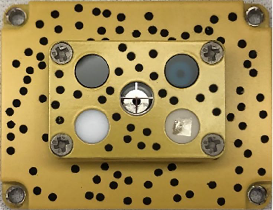
1. A Polytetrafluoroethylene (PTFE) disk to provide a blank specimen which can verify X-ray detection of trace elements. It also gives a broadband X-ray backscatter for verifying the stability of the X-ray source spectrum. If any changes occur, it will be used for tracking those changes as well as any effects of dust on the target.
2. A glass version of the United States Geological Survey (USGS) basaltic standard BHVO‐2, which was specially-prepared by the USGS as a large glass piece by melting and then rapidly quenching powdered BHVO-2 in a platinum boat. BHVO-2 has a known signature of strong peaks typical of basaltic materials and, as a glass, it has excellent homogeneity and stability. Its peak signature provides a reliable energy calibration and the certified concentrations of major, minor, and trace elements provide the main basis for quantitative calibration.
3. A disk of the National Institute of Standards and Technology NIST-610 glass donated by Clay Davis at NIST from their collection. NIST-610 demonstrates strong signals from about 17 geologically important trace elements at concentrations near 400 parts per million. It also contains about 40 other trace elements whose concentrations are not certified but which can be used to verify detection.
4. The mineral scapolite, which was donated by G. Rossman of the California Institute of Technology and embedded in epoxy by the PIXL team. Scapolite demonstrates strong emissions of S and Cl, which are important elements on Mars and present only at trace concentrations in the above standards.
The target at center with a metal cross (a chromium wire in one axis and a nickel wire in the other axis, each 200 μm in width) is used to precisely locate the X-ray beam with respect to the camera. Lastly there is a pseudo-random distribution of 100 black dots against a light background, divided between two surfaces separated by 5 mm in depth. MCC images of these dots allow an accurate estimation of the PIXL sensor head position with respect to the calibration target for checking accuracy of distance measurements made by the SLIs. The target is a passive element that requires no heating.
PIXL Micro Context Camera (MCC)
The PIXL Micro Context Camera (MCC) consists of a power and data processing unit, referred to as MCC Electronics (MCCE), the camera unit (MCC) together with the two active light sources: Two Structured Light Illuminators (SLI) and a Flood Light Illuminator (FLI). The SLI is directly driven by the MCC, while the FLI has two external electronics (FLIE) that serve as energy storage and control for the FLI. The MCCE is piggyback mounted to the PIXL electronics in the rover’s body, whereas all the optical components are embedded into the PIXL's Sensor Assembly mounted on the turret.
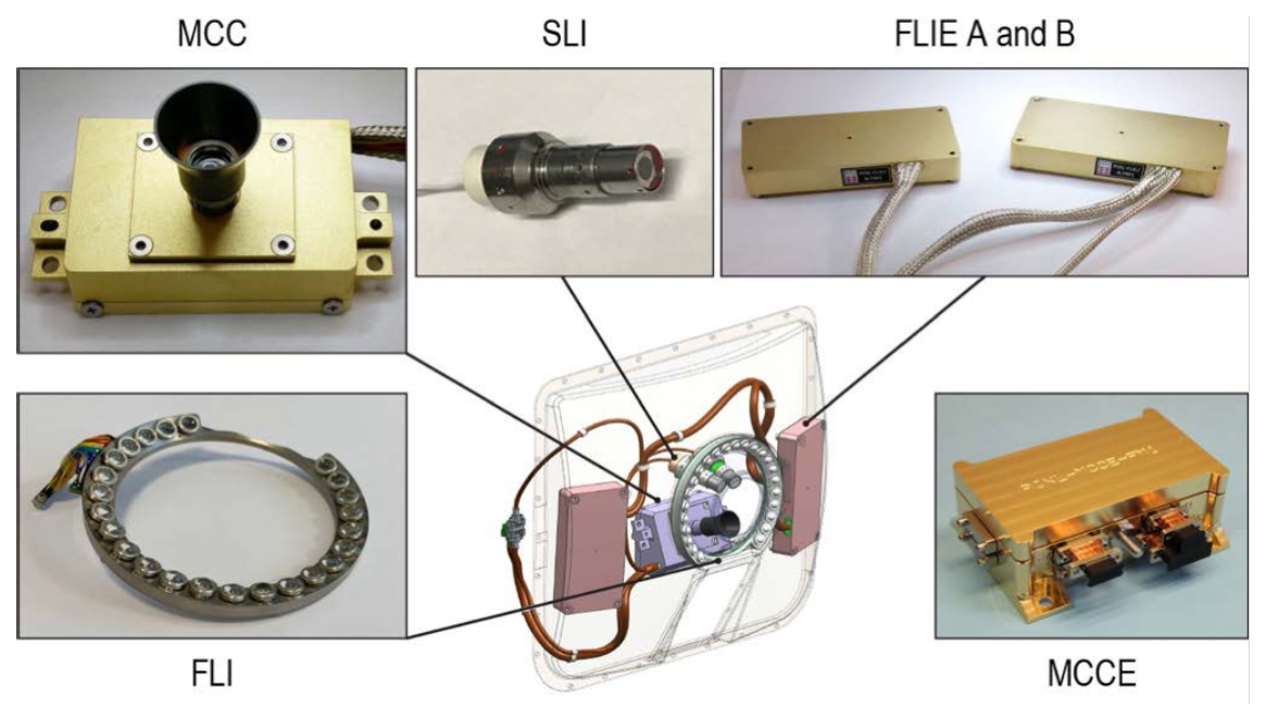
Images of the MCC components and location of sensor head components within the PIXL Sensor Assembly
| PIXL-MCC Operational Characteristics | |
|---|---|
| Characteristic | Value |
| Resolution (S x L) | 752 x 580 |
| Bit Depth | 8 |
| Field of View (FOV) |
37.6 deg x 28.4 deg
~39 mm x 31 mm |
| CCD Pixel Spatial Resolution | 8.6 μm/pixel x 8.3 μm/pixel |
| Effective Focal Length | ~9.5 mm |
| Angular Resolution | 0.052 deg x 0.050 deg |
| Image Resolution | 52 μm/pixel at nominal standoff of 25.5 mm |
| Spectral Wavelength | Continuous in the visible spectrum, reaching from NUV to NIR |
| Number of Spectral Filters | 0 (monochrome detector) |
The light sensitive device of the MCC is a CCD with the physical dimensions of 7.95 mm x 6.45 mm, with 752 x 580 pixels, each pixel being 8.6 x 8.3 μm. The camera optical lens has an effective focal length of ~9.5 mm. The CCD is tilted 5.2 degrees relative to the boresight in order to maintain an angled depth of focus (Scheimplug Principle), complying with the angled perspective when the PIXL Sensor Assembly is oriented perpendicular to the targeted surface. The FLI has LEDs in 4 color channels Red (735 nm), Green (530 nm), Blue (450 nm) and UV (385 nm). Each channel has 6 LEDs and each color can be controlled individually. Furthermore, all the Green LEDs can be individually controlled.
Control of whether to use specific color channel, is achieved by setting the current level for each LED string. To disable/enable a specific string, the current is set to one of the four available levels: 0mA, 140mA, 280mA and 500mA. The figure below provides the mapping of LED IDs on the FLI and an overview of the arrangement of the LED relative to the output strings from FLIE A and FLIE B.
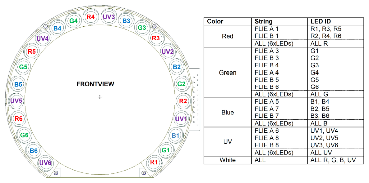
LED distribution on the FLI and corresponding LED ID